
The Making of a School Telescope – Part 1
Article by Mr Gareth Barry
One of the common complaints amongst students is a lack of practical application of the knowledge and skills learnt in class. At St Charles College, we address this by providing as many opportunities as possible for our boys to put their acquired theory into practice. For example in bridge-building and
hydrology competitions, science and enviro-club to name but a few. This year, I decided to involve a group of boys in the building of a telescope for the school. This will provide an opportunity for the boys to learn about the fabrication processes involved, be rewarded with the chance to view the heavens with an instrument made by their own hands, as well as leaving something tangible for future
generations of learners to enjoy.
For a very quick overview of the action of the telescope we will construct, see the diagram below.


The process starts by grinding a suitably thick piece of glass. The larger the diameter of the glass, the greater the power of the instrument, but the greater the labour of grinding! I settled on a 250mm diameter
mirror. A telescope with a mirror of this size will most often be limited by the atmosphere as opposed to the power of the telescope itself.
A diamond coated angle grinder blade is manually stroked across the mirror, taking care to rotate the mirror every few strokes. The action of rotating the mirror at the same time as grinding it forces the mirror to be rotationally symmetrical, i.e. free of astigmatism. This process is
continued until a curve of the required depth is ground into glass.
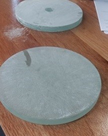
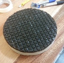
The rough ground glass is shown on the right. At this point, the surface of the glass is extremely rough. In order to reach the extreme smoothness required, a grinding tool is made from plaster-of-paris, with glass tiles glued on. In order to
ensure that the grinding tool has the same curve as the mirror, a ‘dam wall’ of cardboard is taped around the mirror, the plaster is poured over the mirror and allowed to set. Finally, the glass tiles are glued on, at which point grinding can proceed. Silicon carbide abrasive mixed with water is sprinkled on the surface of the mirror. The grinding tool is again stroked across the glass mirror taking care to periodically rotate the mirror. This is continued through finer and finer abrasives, finishing off with 1200 grit.

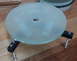
Shown opposite is the finely ground mirror, next to the
previously mentioned grinding tool. By making the strokes with the grinding tool of the appropriate length, a perfectly spherical surface is assured.
At this point, the mirror is ready for polishing. The grinding tool must now be replaced with a polishing tool. Pitch, bitumen or tar has the property of being an extremely viscous liquid. Thus, it is able to ‘flow’ to match the surface of the mirror.

Once again, a plaster tool is cast. The pitch is heated and poured over the tool, and then pressed onto the mirror whilst warm. Channels are cut into the surface of the pitch in order to ensure that it achieves conformity with the mirror whilst being used. The pitch-polisher is stroked over the mirror, using a
polishing compound such as cerium oxide. This is continued until the front surface of the mirror becomes completely
invisible. In fact, a laser shone onto the surface of the mirror should pass completely through, the point of entry into the glass being invisible. 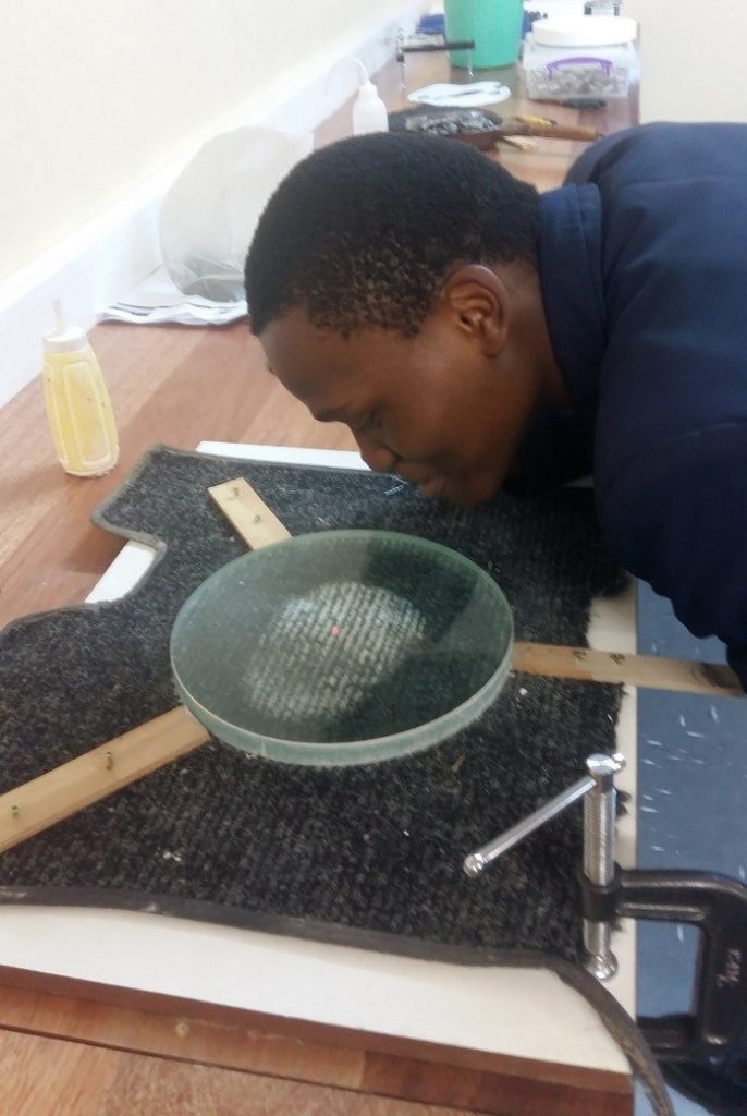
At this point we decided to take a break from the tedium of grinding and
polishing and rather work on the
components that hold the optical parts in place. The mounting system must be stiff yet accommodate any
expansion of the glass due to thermal effects. It must also be adjustable for tilt along three axes.
I decided to call in the help of the practical department of the school and must express my gratitude to
Mr Barrable and his learners for doing an absolutely stellar job in fabricating the mirror holder.
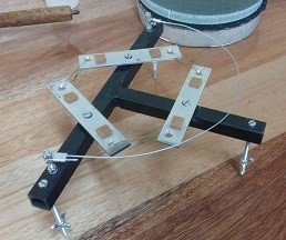
Essentially, the mirror mount or ‘cell’ as it is referred, consists of a steel frame with loosely bolted metal plates. Six small pieces of felt arranged into a hexagonal pattern on the plates support the underside of the mirror, whilst a metal sling supports the side. Three bolts provide the adjustment for tilt.
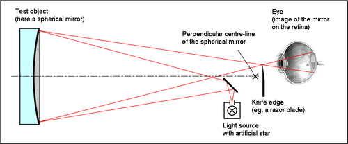
 The well-polished mirror is indeed a thing of beauty. But how to test the surface accuracy? Credit here goes to the 19th century physicist Jean Foucault, who incidentally was the first person to accurately measure the speed of light.
Essentially, light from a small source is placed at the centre of
curvature of the mirror. If the mirror is perfectly spherical, every ray of light will reflect back to a point very near the source.
If a knife edge is then drawn across the point of focus of the return beam, the resulting shadow should cause uniform greying out over the mirror’s surface. It is somewhat amazing that this rather crude
apparatus is capable of testing the surface of the mirror down to the level of a few nanometers!
Thus there is an effective and simple method available for testing a
spherical surface. Unfortunately, a spherical surface will not focus light from a distant star to a sharp focus-the required surface is in fact a
parabola. Thus, the spherical surface must be adjusted to a parabolic one, which is achieved using an appropriate stroke with the polisher, testing regularly. Thankfully, the knife-edge test can be altered slightly in order to confirm that the mirror is in fact parabolic.
The coming weeks will see the boys building the rest of the parts for the telescope. Ultimately, we hope to build two telescopes; one optimized for visual use and the other for astrophotography. Stay tuned for part 2!